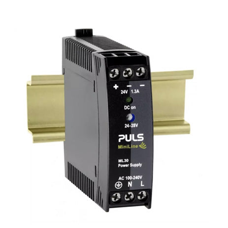
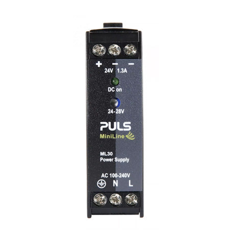
- 100-240V Wide range input
- Adjustable 24-28 output voltage
- Efficiency up to 89.4%
- Electronically protected against overload, no-load and short-circuits
- Output over-voltage protection
- Metal Oxide Varistor for input transient protection
- Isolation resistance safety feature
- 22.5mm Compact design with multiple mounting operations and orientations
- Wide operating temperature of -10C to 70°C
- NEC Class2 compliant, Industrial certification by UL, DNV, Class 1 Div2 and more
PULS MiniLine ML30.241 is a compact and lightweight 24V, 1.3A (30 Watt) industrial din rail power supply for 1 phase system. PULS ML30.241 features quality components and is certified for deployment in hazardous location areas (Class 1 Div 2, DNV and more). PULS ML30.241 offers superior safety features such as output over-voltage protection, input transient protection, isolation resistance safety feature and more. The supplementary MiniLine redundancy module MLY10.241 allows building of redundant systems or to protect against back-feeding voltages. There are several operation modes.
Operation Mode 1: Parallel Use to Increase Output Power
ML30.241 power supplies can be paralleled to increase the output power. This power supply has no feature included which balances the load current between the power supplies. Usually the power supply with the higher adjusted output voltage draws current until it goes into current limitation. This means no harm to this power supply as long as the ambient temperature stays below 45°C.
Puls ML30.241 can also be paralleled with other power supplies from MiniLine series with 24V output voltage. The output voltages of all power supplies shall be adjusted to the same value (±100mV). A fuse or diode on the output of each unit is only required if more than three units are connected in parallel. If a fuse (or circuit breaker) is used, choose one with approximately 150% of the rated output current of one power supply. Keep an installation clearance of 15mm (left / right) between two power supplies and avoid installing the power supplies on top of each other. Do not use power supplies in parallel in mounting orientations other than the standard mounting orientation (input terminals on the bottom and output terminals on top of the unit). Be aware that leakage current, EMI, inrush current and harmonics will increase when using multiple power supplies in parallel.
Operation Mode 2: Parallel Use for Redundancy
Power supplies can be paralleled for redundancy to gain higher system availability. Redundant systems require a certain amount of extra power to support the load in case one power supply unit fails. The simplest way is to put two power supplies in parallel. This is called a 1+1 redundancy. In case one power supply unit fails, the other one is automatically able to support the load current without any interruption. Redundant systems for a higher power demand are usually built in an N+1 method. E.g. five power supplies, each rated for 1.3A are paralleled to build a 5A redundant system.
Operation Mode 3: Series Operation
Power supplies of the exact same type can be connected in series for higher output voltages. It is possible to connect as many units in series as needed, providing the sum of the output voltage does not exceed 150Vdc. Voltages with a potential above 60Vdc are not SELV any more and can be dangerous. Such voltages must be installed with a protection against touching. Earthing of the output is required when the sum of the output voltage is above 60Vdc. Avoid return voltage (e.g. from a decelerating motor or battery) which is applied to the output terminals. Keep an installation clearance of 15mm (left / right) between two power supplies and avoid installing the power supplies on top of each other. Do not use power supplies in series in mounting orientations other than the standard mounting orientation (input terminals on the bottom and output terminals on top of the unit). Be ware that leakage current, EMI, inrush current and harmonics will increase when using multiple power supplies series.
Operation Mode 4: Operation on Two Phases
The power supply can also be used on two-phases of a three-phase-system. A phase-to-phase connection is allowed as long as the supplying voltage is below 240V+10%. Use a fuse or a circuit breaker to protect the N input. The N input is not internally protected and is in this case connected to a hot wire.
This product is export-ready and classified under an international HS Code for smooth customs clearance. TNS ships worldwide via DHL Express, providing fast and reliable international delivery.
For customers in Singapore, we offer free local shipping on orders above SGD $80 — no extra handling fees.
Please contact TNS for key shipping and compliance details to support both local and international logistics planning.


